
1.3 GHz Wireless AV set - Summary
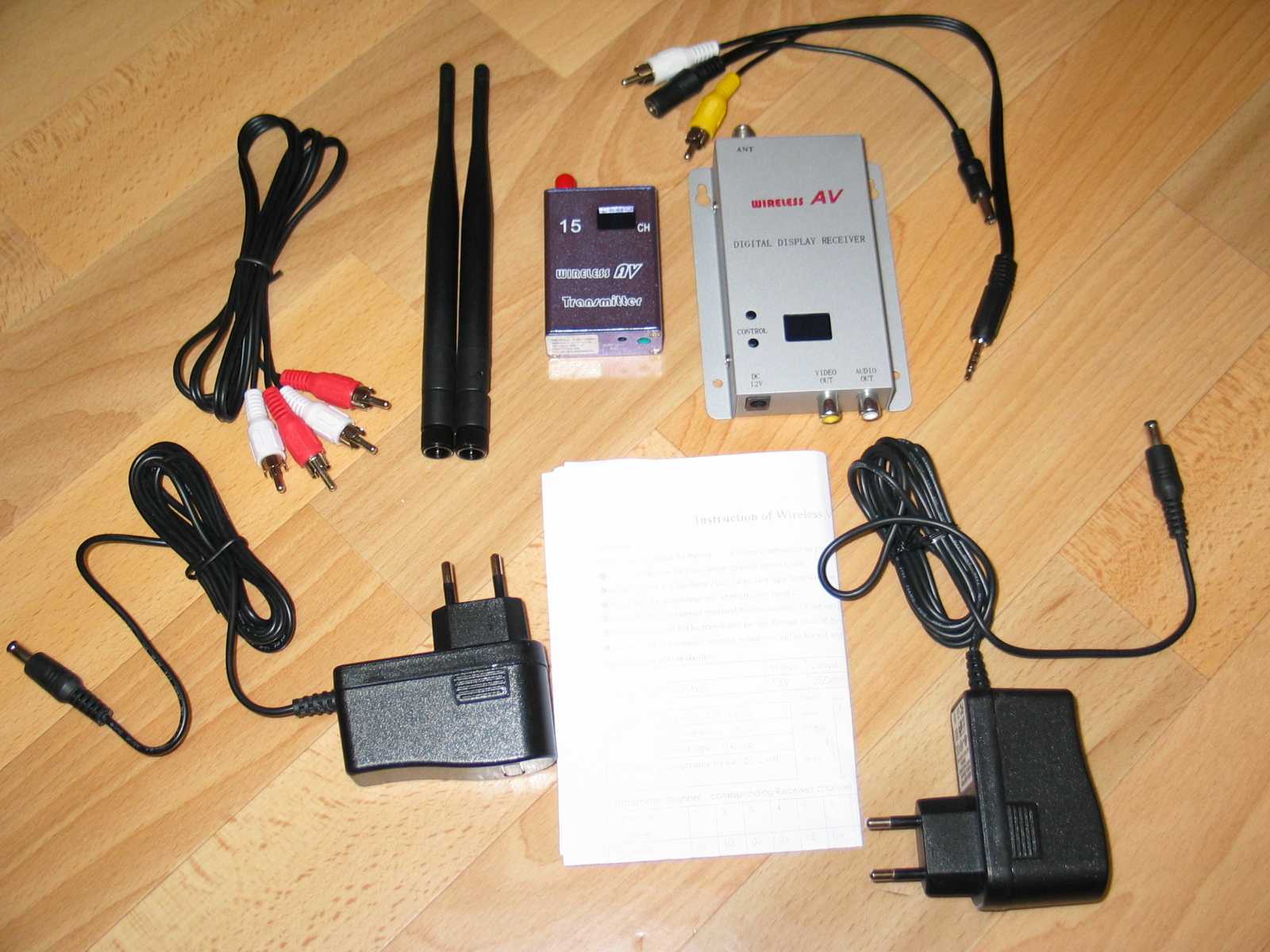
Here is a little summary about the following 1.3 GHz Wireless AV set:
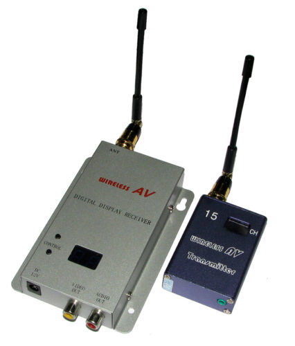
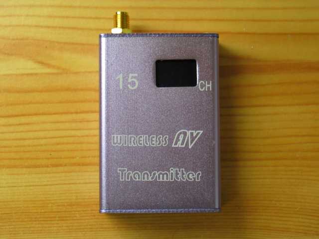
Transmitter #
Technical details:
- Supply voltage 12V
- Supply current 280mA
- Output power <28.5dBm
- Size 65x50x20mm
- Weight (measured) 62g complete; bare PCB 10g
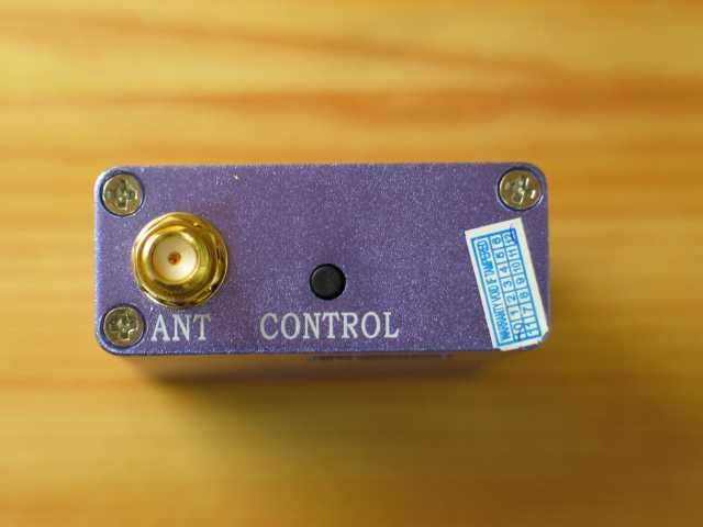
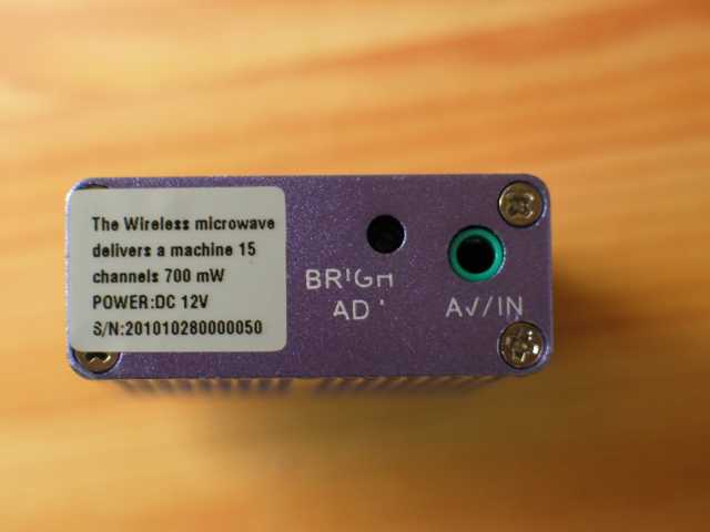
- SMA antenna connector
- 3.5mm 4 pin AV+power jack
- Gain adjustable
- One button control
- 15 Channels
Externals: #
Internals: #
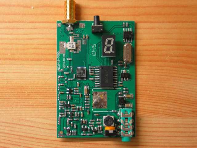
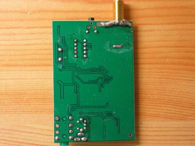
As you can see there is no extra shielding around the PCB. Heat dissipation is mainly done through the bottom side of the PCB.
Some details about the components:
- Philips TSA5520 1.3 GHz universal bus-controlled TV synthesizer
- Futjitsu FLU10 RF power amplifier
- 24C02B EEPROM
- uC marked JX903D
Interesting is the separate EEPROM. Obviously the channel is stored inside. The EEPROM is used only to store the selected channel. The channel will be read on power up and stored on new selection.
Channel	Frequency [MHz]	Power [dBm]
1	993	28.3
2	1020	28.4
3	1050	28.3
4	1060	28.2
5	1080	28.2
6	1100	28.0
7	1120	28.0
8	1140	28.2
9	1160	28.6
A	1180	28.7
B	1200	28.6
C	1220	28.3
D	1240	27.9
E	1256	27.6
F	1280	27.3
Harmonic Distortion:
- 28.04 dBm @ 992.97 MHz
- -13.51 dBc @ 1.99 GHz
- -16.15 dBc @ 2.98 GHz
Receiver #
The receiver is similar to many others coming with such wireless AV sets. You have two buttons to control the receiver, one to cycle channels and a second to store channels for auto cycle.
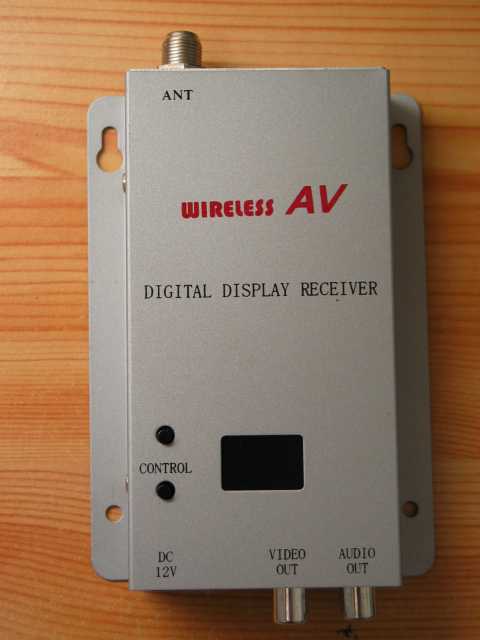
A very interesting fact: The receiver is rated for the frequency range 0.9 - 1.56 GHz, split into 28 channels!
Channel	Frequency [MHz]
1	921
2	993
3	1022
4	1051
5	1062
6	1081
7	1100
8	1120
9	1140
10	1160
11	1180
12	1200
13	1220
14	1240
15	1256
16	1280
17	1300
18	1320
19	1340
20	1360
21	1380
22	1400
23	1420
24	1440
25	1460
26	1480
27	1500
28	1520
Internals: #
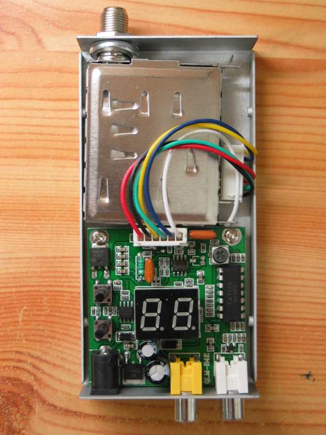
The quality of the PCB looks much better on this receiver than on others I have seen so far. A large spring washer keeps the tuner module in place. But it's also the first one with separate video amplifier. By default the gain of the video amplifier is fixed. But there are pads to solder a potentiometer (2KOhm) to adjust video signal level. Very useful if you drive more than one video input in parallel from the receiver.
Some details about the components:
- TA7176 IF Amplifier+FM Detector
- EEPROM 24C02B
- Philips NE592D Video amplifier
- uC without marking
- 78M05 + 78M09 Linear voltage regulators
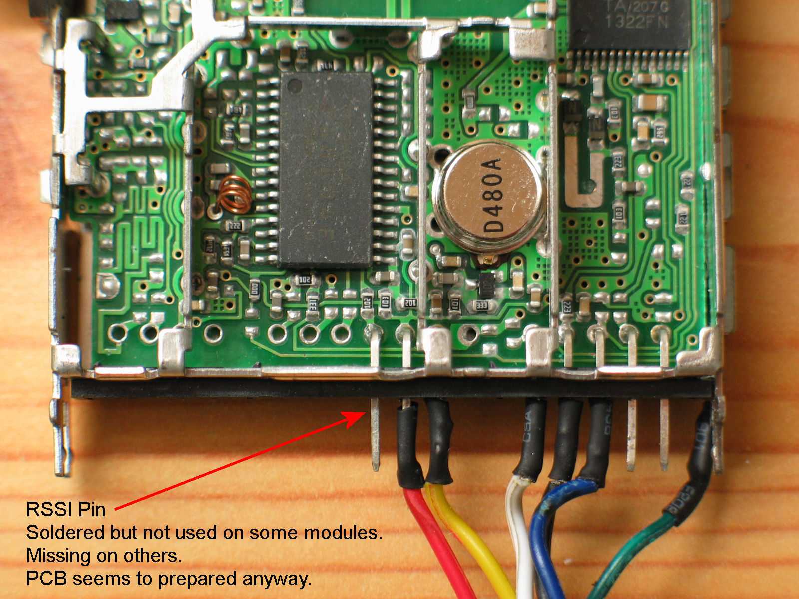
The tuner module is common standard but the RSSI output pin is missing. You need to solder one yourself, the PCB is already prepared. See picture below.
Level [dBm] 	RSSI [V]
-115		0,786
-110		0,784
-105		0,781
-100		0,771
-95		0,758
-90		0,789
-85		0,938
-83,5		1,000
-80		1,160
-75		1,382
-70		1,601
-65		1,810
-60		3,370
-55		3,570
-50		3,660
-45		3,710
-40		3,750
-35		3,790
-30		3,870
-29		3,940
-25		4,340
-20		4,340
The tuner uses the common TA1322FN Down converter in combination with a TA8804F FM demodulator. A 27MHz SAW filter ECS-D479.5B is used in the tuner. (Should be replaced by a ECS-D480A with 17MHz)
Antennas #
No idea here. These antennas are usually crap so I will not test them for VSWR. Better stick with an Yagi and the Inverted-V.
Conclusion #
With some rework this wireless AV set has a big potential for hacking and customizing.
A separate shielding box needs to be made for the receiver. 65g for the original one is a way to much to carry up in the air. Also heat dissipation can be improved this way. All in all I think that's a good set, good hardware potential and better quality than I have seen before.
👈 Home