
LT8490 MPPT Solar Charger
Finally I finished the prototype for the MPPT solar charger board with new Linear LT8490.
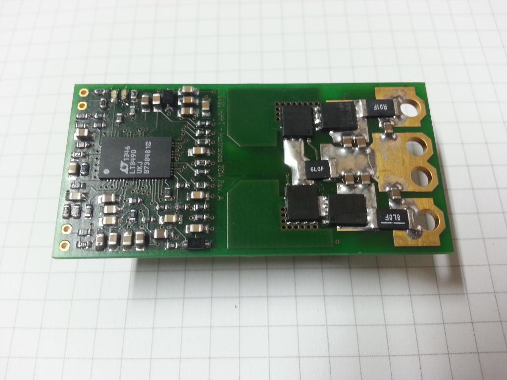
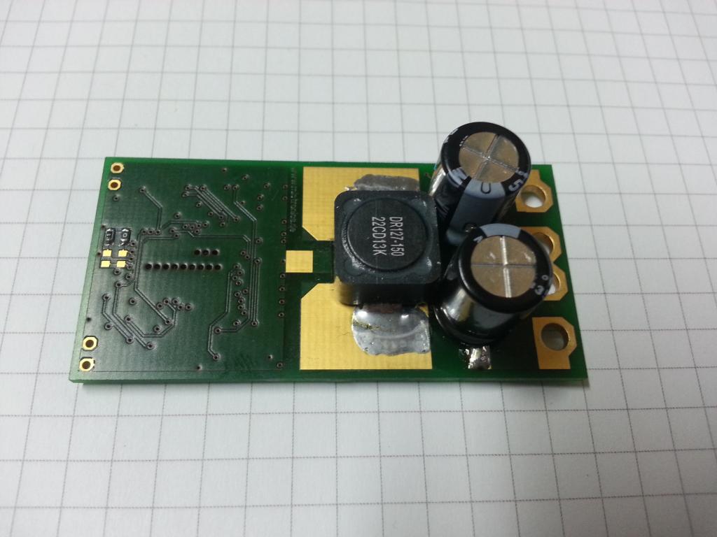
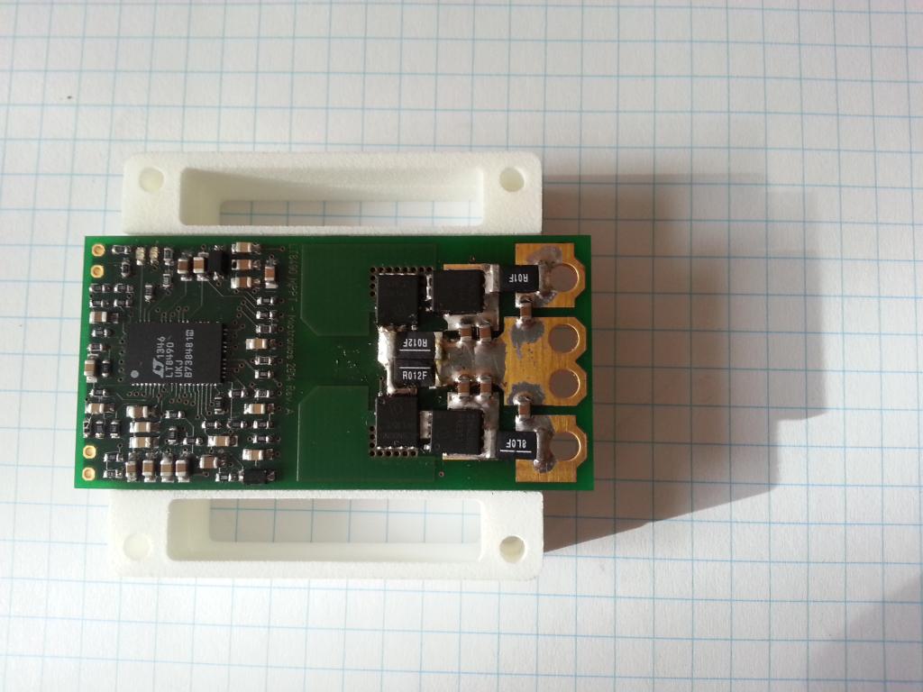
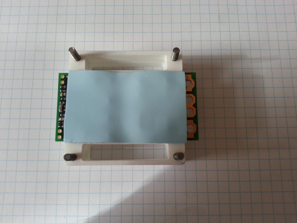
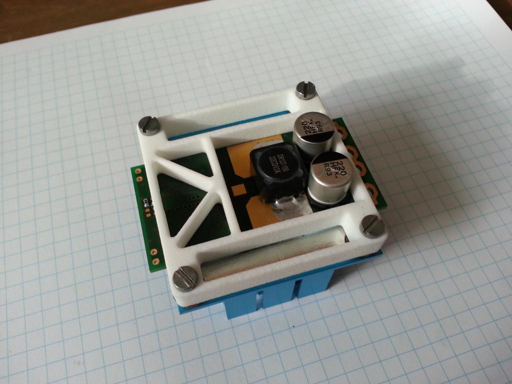
It´s a 4-layer board with a size of 30mm * 60mm, height about 15mm with correct SMD capacitors (those on the picture are temporary). The board is designed to connect battery and solar panel with terminal lugs, the UART output is available, there are two LEDs (status and fault), battery temperature sensor input and the component side is equally flat for attachment to a heat sink.
Special thanks to Tage Bjorklund from Linear Technology for support and recommendations on the board layout (which is indeed critical due to high currents and sensitivity to noise).
The board passed some initial tests with a 3S LiPo configuration. Here are a few numbers with different solar panel voltages.
Solar Input	Battery Output
28,3V/0,5A	11,95V/0,95A
31,3V/0,6A	11,99V/1,20A
33,5V/0,47A	11,99V/1,28A
33,1V/1,1A	11,99V/2,7A
33,7V/0,6A	11,99V/1,75A
21,3V/1,65A	11,98V/2,69A
18,5V/0,35A	11,6V/0,6A
21,7V/1,29A	11,98V/2,34A
10,8V/1,05A	11,99V/1,3A
10,7V/1,02A	11,96V/0,9A
10,77V/0,99A	11,95V/0,95A
The Linear Technology LT8490 is a synchronous buck-boost battery charging controller for lead acid and Lithium batteries, featuring automatic maximum power point tracking (MPPT) and temperature compensation. The device operates from input voltages above, below or equal to the regulated battery float voltage. The LT8490’s full-featured battery charger offers many selectable constant-current constant-voltage (CC-CV) charging profiles, making it ideal for charging a variety of Lithium or lead acid chemistry types, including sealed lead acid, gel cells and flooded cells. All charge termination algorithms are provided onboard, eliminating the need for software or firmware and thus reducing design cycle time.
The LT8490 operates over a wide 6V to 80V input voltage range and can produce a 1.3V to 80V battery float voltage output using a single inductor with 4-switch synchronous rectification. The device is capable of charging currents as high as 10A depending on the choice of external FETs. The LT8490’s MPPT circuit enables a sweep of the full operating range of a solar panel, finding the true maximum power point, even in the presence of local maxima points caused by partial shading of the panel. Once the true maximum power point is found, the LT8490 will operate at that point while using a dithering technique to quickly track changes in the local maximum power point. With this methodology, the LT8490 fully utilizes the power generated by a solar panel even in non ideal operating environments.
The LT8490 performs automatic temperature compensation of the battery charge voltage by sensing an external thermistor on the battery. The STATUS and FAULT pins can be used to drive LED indicator lamps. Charging current limits can be adjusted by changing as few as 1 or 2 resistors, and a charging time scale can be selected with the appropriate resistor divider.
My LT8490 design follows closely the recommendation from Linear Technology. The schematic was designed in reference to the examples from datasheet and demo board. For the board layout I got help from a nice Linear guy, Tage Bjorklund, who previewed the layout a few times to ensure a proper design for high currents and low noise.
Down below are some design documents available for download. The BOM files including order numbers for all parts from Digikey. To design a charger for your own requirements a spread sheet (LibreOffice) is available to calculate all components that have an influence on the charging parameters.
CAD files for the layout will be not available any time soon. The board is a 4-layer design and requires a manufacturer who can handle the specifications for that, they are not cheap when ordered in a low count. I will probably sale the boards for a reasonable price when manufactured in a large number.
The photos are showing the prototype design with a size of 30mm*60mm and a height of about 15mm. The board will not be modified, wasting empty board space just to provide four mounting holes isn't a cheap solution on a 4-layer design. Instead I have designed a frame that allows attachment to a 50x50mm heatsink. The frame is available at Shapeways.
Optional Heatsink #
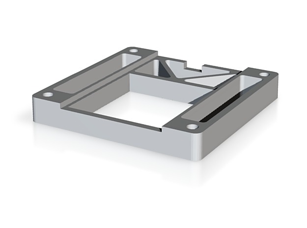
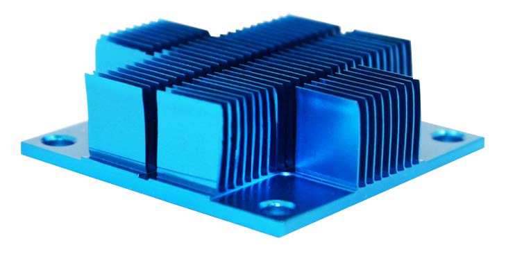
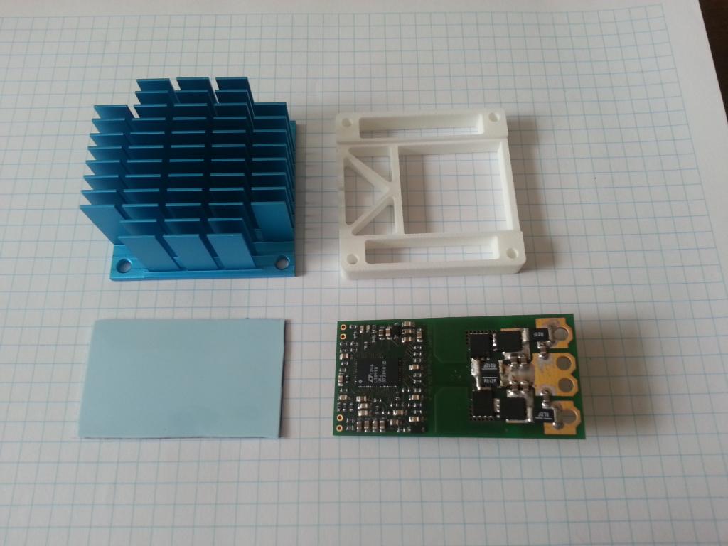

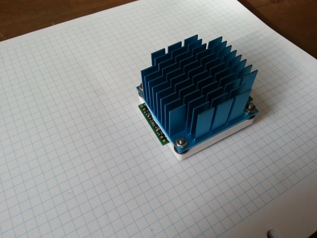
Required parts
- Heatsink, ATS series, 50x50mm, fin height as required, Digikey part number ATS1590-ND
- Heat transfer and isolation sheet, Digikey part number 1168-1978-ND, good for a few boards
Downloads #
Schematic
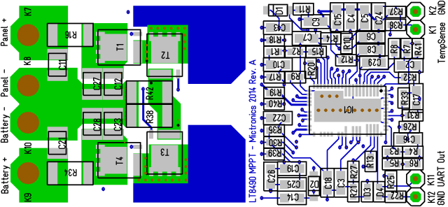
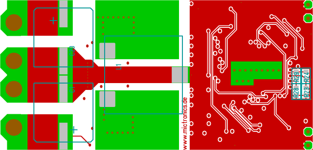
Layout Top
Layout Bottom
BOM 3.6V
BOM 12.6V
BOM 14.2V
LT8490 Calculator
Demo Board Schematic
👈 Home